FunctionalModels.Lib
Examples using models from the FunctionalModels standard library (FunctionalModels.Lib).
Many of these are patterned after the examples in the Modelica Standard Library.
Electrical
CauerLowPassAnalog
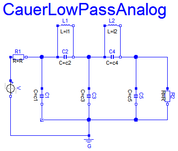
Main.Examples.Lib.CauerLowPassAnalog — FunctionCauer low-pass filter with analog components
The example Cauer Filter is a low-pass-filter of the fifth order. It is realized using an analog network. The voltage source on n1 is the input voltage (step), and n4 is the filter output voltage. The pulse response is calculated.
CauerLowPassOPV
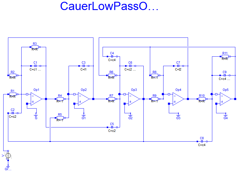
Main.Examples.Lib.CauerLowPassOPV — FunctionCauer low-pass filter with operational amplifiers
The example Cauer Filter is a low-pass-filter of the fifth order. It is realized using an analog network with op amps. The voltage source on n[1] is the input voltage (step), and n[10] is the filter output voltage. The pulse response is calculated.
CauerLowPassOPV2
Main.Examples.Lib.CauerLowPassOPV2 — FunctionCauer low-pass filter with operational amplifiers (alternate implementation)
The example Cauer Filter is a low-pass-filter of the fifth order. It is realized using an analog network with op amps. The voltage source on n1 is the input voltage (step), and n10 is the filter output voltage. The pulse response is calculated.
CharacteristicIdealDiodes
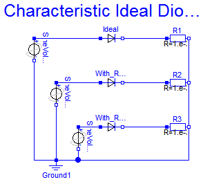
Main.Examples.Lib.CharacteristicIdealDiodes — FunctionCharacteristic of ideal diodes
Three examples of ideal diodes are shown:
- The totally ideal diode (Ideal) with all parameters to be zero
- The nearly ideal diode with Ron=0.1 and Goff=0.1
- The nearly ideal but displaced diode with Vknee=5 and Ron=0.1 and Goff=0.1.
The resistance and conductance are chosen untypically high since the slopes should be seen in the graphics. The voltage across the first diode is (s1 - n1). The current through the first diode is proportional to n1.
ChuaCircuit
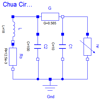
Main.Examples.Lib.ChuaCircuit — FunctionChua's circuit
Chua's circuit is a simple nonlinear circuit which shows chaotic behaviour. The circuit consists of linear basic elements (capacitors, resistor, conductor, inductor), and one nonlinear element, which is called Chua's diode.
To see the chaotic behaviour, plot n2 versus n3 (the two capacitor voltages).
HeatingResistor
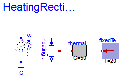
Main.Examples.Lib.HeatingResistor — FunctionHeating resistor
This is a very simple circuit consisting of a voltage source and a resistor. The loss power in the resistor is transported to the environment via its heatPort.
HeatingRectifier
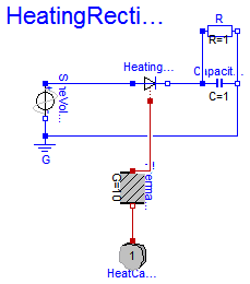
Main.Examples.Lib.HeatingRectifier — FunctionHeating rectifier
The heating rectifier shows a heat flow always if the electrical capacitor is loaded.
Rectifier
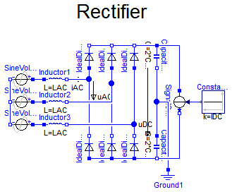
Main.Examples.Lib.Rectifier — FunctionB6 diode bridge
The rectifier example shows a B6 diode bridge fed by a three phase sinusoidal voltage, loaded by a DC current. DC capacitors start at ideal no-load voltage, thus making easier initial transient.
ShowSaturatingInductor
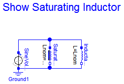
Main.Examples.Lib.ShowSaturatingInductor — FunctionSimple demo to show behaviour of SaturatingInductor component
This simple circuit uses the saturating inductor which has a changing inductivity.
LBL doc link | MapleSoft doc link
NOTE: CURRENTLY BROKEN
ShowVariableResistor
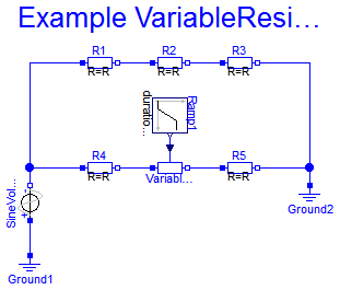
Main.Examples.Lib.ShowVariableResistor — FunctionSimple demo of a VariableResistor model
It is a simple test circuit for the VariableResistor. The VariableResistor sould be compared with R2. isig1 and isig2 are current monitors
ControlledSwitchWithArc
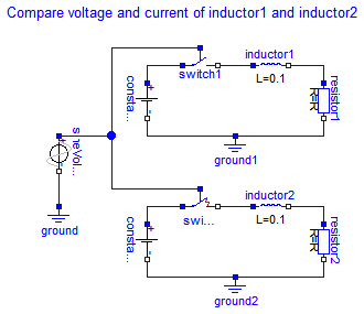
Main.Examples.Lib.ControlledSwitchWithArc — FunctionComparison of controlled switch models both with and without arc
This example is to compare the behaviour of switch models with and without an electric arc taking into consideration.
a3 and b3 are proportional to the switch currents. The difference in the closing area shows that the simple arc model avoids the suddenly switching.
CharacteristicThyristors
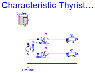
Main.Examples.Lib.CharacteristicThyristors — FunctionCharacteristic of ideal thyristors
Two examples of thyristors are shown: the ideal thyristor and the ideal GTO thyristor with Vknee=5.
Heat transfer
TwoMasses
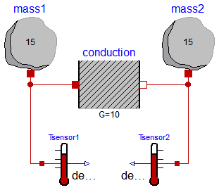
Main.Examples.Lib.TwoMasses — FunctionSimple conduction demo
This example demonstrates the thermal response of two masses connected by a conducting element. The two masses have the same heat capacity but different initial temperatures (T1=100 [degC], T2= 0 [degC]). The mass with the higher temperature will cool off while the mass with the lower temperature heats up. They will each asymptotically approach the calculated temperature TfinalK (TfinaldegC) that results from dividing the total initial energy in the system by the sum of the heat capacities of each element.
Motor
Main.Examples.Lib.Motor — Function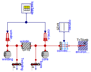
Rotational
First
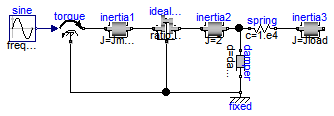
Main.Examples.Lib.First — FunctionFirst example: simple drive train
The drive train consists of a motor inertia which is driven by a sine-wave motor torque. Via a gearbox the rotational energy is transmitted to a load inertia. Elasticity in the gearbox is modeled by a spring element. A linear damper is used to model the damping in the gearbox bearing.
Note, that a force component (like the damper of this example) which is acting between a shaft and the housing has to be fixed in the housing on one side via component Fixed.